 |
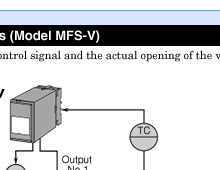
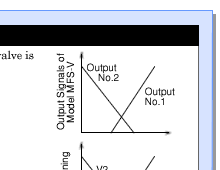
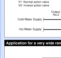
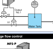
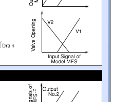
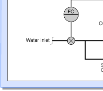
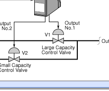
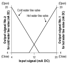
| Figure 1. Operation
of V-shape characteristics Split-Range Transmitter, Model MFS-V. |
| |
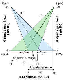 |
| Figure 2. Adjustable
range of V-shape characteristics Split-Range Transmitter, Model MFS-V. |
| |
 |
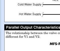
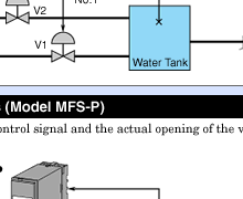
| Figure 3. Operation of parallel characteristics
Split-Range Transmitter, Model MFS-P. |
| |
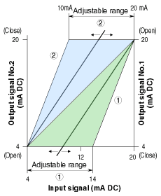 |
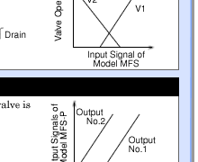
| Figure 4. Adjustable range of parallel characteristics
Split-Range Transmitter, Model MFS-P. |
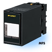
The Model MFS Split-Range Transmitter is a signal conditioner that can be used
to manipulate two control valves with only one input signal. This type of function
is usually obtained by using a valve positioner’s split ranging action. However,
by using the Model MFS, ordinary control valves that are configured for a 4 –
20 mA input can be used for this purpose. As for the characteristics combination
of two control output signals, V-shape (inverse) and parallel types are offered.
Either one can be used depending on the valve’s operating direction. With
a DCS, the number of control outputs can be reduced from two to one if the Model
MFS is used.
The V-shape characteristics model (Model MFS-V) is typically used when temperature
is controlled by using hot and cold water, and either line valve has the same
opening direction in relation to the input signal. As an example, a cold water
line valve is controlled from fully open to closed with the input signal range
of 4 – 12 mA DC while the hot water line valve is controlled from closed
to fully open with the input signal range of 12 – 20 mA DC (See Figure 1).
With the Model MFS-V, 0% (4 mA) on output signal No.2 can be adjusted over the
input range of 10 – 20 mA DC. In the same manner, 0% (4 mA) on output signal
No.1 can be adjusted over the input range of 4 – 14 mA DC. That is to say,
the Model MFS provides the flexibility to adjust both outputs so that there is
some overlap between them (See Figure 2).
The parallel characteristics model (Model MFS-P) is typically used when temperature
is controlled by using hot and cold water where these line valves have different
opening directions in relation to their respective input signals. For example,
a cold water line valve is controlled from fully open to closed with the input
signal range of 4 – 12 mA DC while the hot water line valve is controlled
from closed to fully open with the input signal range of 12 – 20 mA DC (See
Figure 3).
With the Model MFS-P, 100% (20 mA) on output signal No.2 can be adjusted over
the input range of 10 – 20 mA DC. In the same manner, 0% (4 mA) on output
signal No.1 can be adjusted over the input range of 4 – 14 mA DC. This shows
that the Model MFS provides the flexibility to adjust both outputs so that there
is some overlap between them (See Figure 4). |
