New Products Release
Analog Backup Station (with bargraph/digital indicator)
Model ABF3 Release : NOW   RoHS
Delivery : 7 working days SpecClick here to view specification sheet in PDF format.
Paperless Recorder (built-in input modules, 2-point inputs)
Model 73VR2102 Release : NOW    
Delivery : 7 working days SpecClick here to view specification sheet in PDF format.
Paperless Recorder (built-in input modules, 4-point inputs)
Model 73VR2104 Release : NOW    
Delivery : 7 working days SpecClick here to view specification sheet in PDF format.
Paperless Recorder (built-in input modules, 6-point inputs)
Model 73VR2106 Release : NOW    
Delivery : 7 working days SpecClick here to view specification sheet in PDF format.
Paperless Recorder (selectable input modules)
Model 73VR3100 Release : NOW    
Delivery : 12 working days SpecClick here to view specification sheet in PDF format.
Multi Power Input Module
Model R3-WT1 Release : NOW   RoHS
Delivery : 7 working days SpecClick here to view specification sheet in PDF format.
AC Power Input Module (4 input circuits, clamp-on current sensor type CLSA use)
Model R3-WT4A Release : NOW   RoHS
Delivery : 7 working days SpecClick here to view specification sheet in PDF format.
AC Power Input Module (4 input circuits, clamp-on current sensor type CLSB use)
Model R3-WT4B Release : NOW   RoHS
Delivery : 7 working days SpecClick here to view specification sheet in PDF format.
Encoder Speed Transmitter (PC programmable; built-in escitation)
Model M2XRP2 Release : NOW   RoHS
Delivery : 6 working days SpecClick here to view specification sheet in PDF format.
Thermocouple Input Module (re-transmitted output)
Model R5-TS1A Release : NOW RoHS
Delivery : 9 working days SpecClick here to view specification sheet in PDF format.
Lightning Surge Protector for Ethernet (100 BASE-TX / 10 BASE-T)
Model MDM5E-A Release : NOW   RoHS
Delivery : 6 working days SpecClick here to view specification sheet in PDF format.
Clamp-on Current Sensor (1A output)
Model CLSD Release : NOW   RoHS
Delivery : 4 working days SpecClick here to view specification sheet in PDF format.
Modbus I/O Module
Model R7M Release : NOW RoHS
Delivery : 7 working days SpecClick here to view specification sheet in PDF format.
Base (FOUNDATION Fieldbus Power Supply Unit)
Model FFBS Release : NOW  
Delivery : 6 working days SpecClick here to view specification sheet in PDF format.
Diagnostic Module (FOUNDATION Fieldbus Power Supply Unit)
Model FFDG Release : NOW  
Delivery : 6 working days SpecClick here to view specification sheet in PDF format.
Power Supply Module (FOUNDATION Fieldbus Power Supply Unit)
Model FFPS Release : NOW  
Delivery : 6 working days SpecClick here to view specification sheet in PDF format.
FOUNDATION Fieldbus Power Supply Unit
Model FFPSU Release : NOW  
Delivery : 6 working days SpecClick here to view specification sheet in PDF format.


Featured Products

Best suited to record data transmitted from remote I/O located remotely in the field, or within an instrumentation cabinet.

1. Features

  • Up to 128 channels can be monitored
  • 73VR1100 connects to a wide selection of M-System’s remote I/O modules.
  • Instead of using expensive sensor cables, reduce wiring runs by using open field networks through remote I/O.
  • I/O separated 73VR1100 provides the installation flexibility which fits in the tight space of a control panel or machinery chassis.
  • Simple graphic panel produce customizable displays that show specific processes.
  • Comment: Shows comments entered manually. Comment History View: Shows data stored in the comment history file.
Table 1. Comparison of 73VR1100, 73VR2100, and 73VR3100 Specifications
Model 73VR1100 73VR2100 73VR3100
No. of input pen points 64, 128
(including calculation function pen points)
2, 4, 6, 8, 10, 12 4 to 64
No. of calculation function pen points 32, 64 12 16, 64
Data storing rate (high-speed mode) 100 ms 20 ms/100 ms
Data storing rate (normal mode) 0.5, 1, 2, 5, 10 sec; 1, 10 min
Input signals Selected with remote I/O. Universal input Selected with R3 Series I/O card.
DC voltage and current; Thermocouple; RTD; D I/O; totalized pulse; AC voltage, current, power and others. DC voltage, thermocouple, RTD, D I/O DC voltage and current; thermocouple; RTD; D I/O; totalized pulse; AC voltage, current, power and others.
Trigger input (recorder) None 1 None
Alarm output, Error output (recorder) Alarm output x 1;
Error output x 1
Alarm output x 1
(also used as Error output)
None
External dimensions W144 x H144 x D133 mm W144 x H144 x D172 mm W144 x H144 x D245.1 mm
Weight Approx. 1.7 kg Approx. 2.3 kg Approx. 2.3 kg (excluding I/O card)
Display Display device 5.5-inch TFT LCD
Display colors 256
Resolution 320 x 240 pixels
Pixel pitch 0.12 x 0.35 mm
Backlight Cold-cathode tube
Interface Ethernet 10BASE-T/100BASE-TX (auto-sensing); conforms to IEEE 802 and IEEE 802.3
RS-485 38,400 bps
IP address 192.168.0.1 (factory setting)
CF card slots 1 slot (supports Type 1 cards)
Supports cards with an operating voltage of 3.3 V
USB Conforms to Version 1.1
Power supply AC power supply: 100 to 240 V
DC power supply: 24 V
Dustproof and drip-proof specifications Conforms to IP65
(applicable to the front panel of the recorder with single mounting according to the specified panel cutout, not apply to clustered mounting)
Included software Builder Software 73VR11BLD: Builder Software
(for device configuration)
73VR21BLD: Builder Software
(for device configuration)
73VR31BLD: Builder Software
(for device configuration)
Data Viewer 73VRWV: Data Viewer (for displaying and analyzing recorded data)
Recorder MSR128: PC recorder software
Other Includes comment insertion function; support for graphic views. Includes comment insertion function. PLC connection supported.

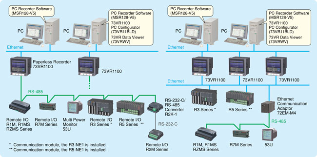
2. System Configuration (1)
Connecting the 73VR1100 to One or More Remote I/O Devices
Figure 1. Illustrates an Example System Configuration Using the 73VR1100

  • Data from remote I/O devices connected via Ethernet or RS-485 can be recorded.
  • High speed mode, 100 msec. storing rate for the max. of 64 points (1 station) with the R3-NE1 module (RS-485 connectivity is not supported).
  • During normal sampling (0.5 sec to 10 min), either two R3 remote I/O Series stations can be connected via Ethernet, or up to 15 remote I/O devices via RS-485. However, a single 73VR1100 recorder cannot accommodate remote I/O connections via both Ethernet and RS-485.
  • An Ethernet Communication Adapter (model: 72EM-M4) can be used to connect RS-485 devices via Ethernet. Up to 15 devices can be connected to a single 72EM-M4 adapter via RS-485.

3. System Configuration (2)
Connecting the 73VR1100 to One or More Computers

  • As with other 73VR Series products, the 73VR product package (model: 73VRPAC2) includes upstream software that runs on a computer.
    Use the PC Recorder Software (MSR128) to record and monitor data with a computer. In this configuration, the 73VR1100 and computer are connected via Ethernet. The MSR128 software’s maximum sampling speed is 0.5 sec. When the 73VR1100 is performing sampling at 100 ms, MSR128 displays and records data every 0.5 sec.
  • Up to four 73VR1100 recorders can be connected to a single computer running the MSR128 software.
    Additionally, the software supports centralized monitoring of up to 128 points.
  • Up to 2 computers running the MSR128 software can be connected to a single 73VR1100 recorder, enabling data to be monitored by computers in 2 separate locations.
  • The product package also includes 73VR1100 Builder Software (73VR11BLD: software for configuring the 73VR1100 using a computer) and 73VR Data Viewer (73VRWV: software providing waveform display, analysis, upload, CSV conversion, and data file segmentation functionality for recorded data).

In the next issue we will discuss supported remote I/O devices, new 73VR Series functionality, simple graphic display functionality, and comment insertion functionality.

(Specifications described in this article are subject to modification. Please confirm the most recent specifications before purchase.)
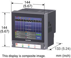

Figure 1. System Configuration


Featured Products
US Distributor Meeting participants
Mr. Darryl Gibbons BDC Inc. (MO)
Mr. John Hermes Control Distributors (AZ)
Mr. Josh Hotvedt Control Distributors (AZ)
Mr. Nick Lukehart Davis Inotek Instruments (TX)
Mr. David Peek, FLW, Inc. (CA)
Mr. Dennis Maurer Fox & Dole Technical Sales (OH)
Mr. Bruce Dye Industrial Equipment Co. (TX)
Mr. Ken Bradway Loy Instrument, Inc. (IN)
Mr. Lee Bethune McGoff-Bethune, Inc. (GA)
Mr. Jose Cantu Saitec Mexicana, S.A. (Mexico)
Mr. Phil Johnson SRP Control Systems Ltd. (Canada)
Mr. Joe Santo SRP Control Systems Ltd. (Canada)
Mr. Tim Millard Synergy Systems Inc. (IL)
Mr. Troy Lainson Meiji Corporation
Mr. Shinji Okazaki Engineering Department,
M-System Co., Ltd.
Mr. Kaz Shimazu M-System Co., Ltd.

M-System’s annual North American distributor meeting was held the 6th of November in Las Vegas, Nevada. The program for the meeting included the following sessions:

  • Introduction of new products including: 73VR2108/2110/2112 & 73VR1100 paperless recorder, M6D & M6N ultra-slim signal conditioners, 27-series head-mount temperature transmitter, SHSP Ethernet switch (w/surge protection).
  • Product updates of 53U multi power monitor, MSR & MSRpro recorder software, MD7 ultra-slim surge protector, and 48N bargraph indicator
  • New sales promotional program
  • M3 and B3 stocking program
  • Sales success stories

Meeting was highly interactive and very productive. We all enjoyed sharing useful marketing and sales ideas. Thank you to each participant for spending your valuable time and money to come to our meeting.

Kaz Shimazu – M-System Co., Ltd. (shimazu@m-system.co.jp)mail
 

The beginning of November brought a great turnout to our Annual Distributor Sales Meeting in LasVegas, NV. We were able to enjoy the beautiful LasVegas weather but only briefly as our day was packed full of new product offerings, updated versions of existing models, such as analog outputs for the highly successful 53U multi-power monitor and additional UL/cUL approvals in process for a wide variety of series. Also, several distributors shared application stories from recent project orders as well as others that reminded us just how many modules that M-System has to suit almost every customer’s need.

Thank you so much to all the attendees for taking time out of your schedule to join us. We are excited to serve you!

Troy Lainson, Operations Manager/Distributor Sales Manager – Meiji Corporation (TroyL@meijicorp.com)mail

Hotline News
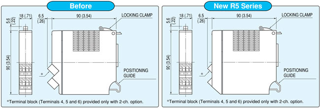
Housing Design Change of Remote I/O, R5 series

To improve visibility of product specifications, we eliminate printed label, and replace to laser printing. We have already changed it on the remote I/O, R5 series. At the same time, we have also changed shapes of heat release slit and screw terminal block on the housing. If you have any questions, please contact
M-System sales or Hotline support personnel.

 
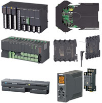
Good Design Award 2007

M-System’s R3, R5, R7, M3 and M6D series proudly received the “Good Design Award” in October 2007.

The “2007 Small and Medium Enterprises Prize” is the official recognition of excellence in design offered by the Japan Industrial Design Promotion Organization (JIDPO)*.

Please check the below address for more details.
––> check!

07A09024, 07A09025, 07A09026, 07A09027, 07A09028, 07A09029
Remote I/O / Universal Transmitter
R3 / R5 / R7 / M3 / M6D / M7E
M-System Co., Ltd.

* Good Design Award is operated by Japan Industrial Design Promotion Organization.

History of Good Design Award - It is Japan’s only comprehensive design evaluation and commendation system. This system itself has its origins in the “Good Design Selection System” (generally known as the “G-Mark System” ) instituted by the Ministry of International Trade and Industry in 1957.


Application Notes

QWe monitor signal from the turbidity meter, which is installed in drain facility.

We have to maintenance/clean up the facility several times per year.

We would like to provide a simulated DC signal to prevent the monitor equipment from detecting abnormal signal from turbidity meter during drain facility maintenance time. As for the simulated DC signal, we would like to change the set point and monitor the value easily. Does M-System have any suitable DC signal generator? We use 4-20mADC signal as turbidity meter output. We can prepare 100VAC power for the generator. We plan to switch from turbidity meter signal to simulated DC signal by using a switching relay.

A Click here for answer


M-System CALENDAR

Offices & Factory Closed
M-System’s offices and factory will be closed from December 29, 2007 to January 6, 2008 for New Year’s Holiday. We will be back again on Monday January 7, 2008.

Also closed on January 14, 2008 for a national holiday.

We will appreciate it if you would kindly keep this in mind when you discuss delivery time with your customers.

January 2008
Mon Tue Wed Thu Fri Sat Sun
Dec 24 25 26 27 28 29 30
31 1 2 3 4 5 6
7 8 9 10 11 12 13
14 15 16 17 18 19 20
21 22 23

24

25 26 27
28 29 30 31 Feb 1 2 3


CLIPBOARD is a newsletter from M-System. Introducing new products, product literature and other important information we pick up in our daily business correspondence. Your comments, views and contribution are especially welcome.

M-System Co., Ltd
International Sales Department
Tel: +81-6/6659-8201 Fax: +81-6/6659-8510 Mail:info@m-system.co.jp