Featured Products
  •  
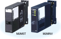
    Figure 1. M2MST, M2MNV External Appearance
    Figure 1. M2MST, M2MNV External Appearance
     
    Parameter Generator (model: M2MST)
  • Analog Switching Module (model: M2MNV)

M-System’s M2 (Mini-M) Series Signal Transmitters are designed to accept a large range of process signal inputs and provide standard and non-standard DC output. The M2 uses a plug-in socket base for quick installation or replacement of modules without disturbing wiring.

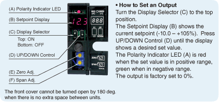
The M2MST (see Figure 1), with Isolation (dielectric strength) of 2000V AC @1 minute (output to power to ground), provides a constant DC signal for a setpoint and is adjusted by pressing the UP/DOWN control switch. The setpoint adjustment is easily accessed by opening the front digital display (Red LED) and the polarity indicator (Red/Green dual color LED, Red with a positive set value; Green with a negative set value). The setpoint is adjustable from –10.0% to +105% (0.1% increments, 1% increments over 100%).

Figure 2. M2MST Front View

For example, the output of M2MST is set at +65.0% when polarity indicator is lit Red and digital display is showing 65.0. To prevent operators from accidentally changing the setpoint by touching the display selector, it can be set to the downside, or OFF position, which disables the setting function and the digital display is turned off. It also has a power saving mode, which enables indicators to turn off when the switches are left untouched for 1 minute at the setting mode.

Table 1. Output
Current Output Voltage Output
4 to 20mA DC
2 to 10mA DC
1 to 5mA DC
0 to 20mA DC
0 to 16mA DC
0 to 10mA DC
0 to 1mA DC
Specify current
 
0 to 10mV DC
0 to 100mV DC
0 to 1V DC
0 to 10V DC
0 to 5V DC
1 to 5V DC
-10 to +10V DC
-5 to +5V DC
Specify voltage

The M2MST output signal is selectable when ordering from Table 1.

The M2MNV switches between two analog signal channels and provides an output.

Isolation (dielectric strength): 2000V AC @1 minute
(switching command contact to power to ground)
  2000V AC @1 minute
(signal channel to power to ground)
  1500V AC @1 minute
(signal channel to switching command contact)
 
Table 2. M2MNV Input & Output
SIGNAL CHANNELS
Max. operational voltage range ±50V DC (min. span 10mV)
Max. operational current range ±50mA DC (min. span 1mA)
Receiving resistor 50Ω incorporated (input code 2)
ON resistance ≤50Ω per wire
(ON resistance of photo MOS relay)
OUTPUT
Current signal input
(no receiving resistor)
Equal to the input signal
Current signal input
(receiving resistor 50Ω)
Voltage signal equal to [Current × 50Ω]
Voltage signal input Equal to the input signal
SWITCHING COMMAND: Relay or open collector
Contact detecting 5V DC / 1mA
Detecting levels ≤1kΩ at ON / ≥10kΩ at OFF
 

The input signal is selectable from three types. When selecting the input code 1, current signal (no receiving resistor), both A1 and A2 lines have Photo MOS relays which functions to short a side of the unswitched signal and prevent it from opening. It also prevents A1 and A2 lines from being open when the power input is OFF.
The switching control is selectable from the following two types.


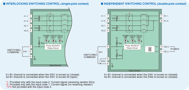
Figure 3. M2MNV Schematic Circuitry & Connection Diagram
 
  CHANNEL 1
(A1)
CHANNEL 2
(A2)
Terminal 3 – 9 ON
(open)
OFF ON
Terminal 3 – 9 ON
(closed)
ON OFF
Status LED turn on when the respective channels are alive.

INTERLOCKING SWITCHING CONTROL
(single-pole contact)

Single contacts are used to switch from Signal Channel 1 (A1-B1) to Signal Channel 2 (A2-B1) and vice versa.


Table 3. Switching Status
  Current Signal
(no receiving resistor)
Current Signal
(receiving resistor 50Ω)
Voltage Signal

Power : OFF
Switching command : OFF (open)

Power : ON
Switching command : OFF (open)

Power : ON
Switching command : ON (short)

  Transition (ON to OFF, OFF to ON) Status
Current Signal
(no receiving resistor)
Current Signal
(receiving resistor 50Ω)
Voltage Signal

Power : ON
Switching command : OFF to ON
or
Power : ON
Switching command : ON to OFF

When the switching command contact is switched from OFF to ON or from ON to OFF, the signal channel is switched only after all photo MOS relays turn on (closed). When the switching command contact is switched from OFF to ON or from ON to OFF, the signal channel is switched only after all photo MOS relays turn off (open).
*1. Resistor is provided only for the input code 2: Current signal (receiving resistor 50Ω).
 
 
  CHANNEL 1 (A1) CHANNEL 2 (A2)
Terminal 3 – 9 OFF (open) OFF ---
Terminal 3 – 9 ON (closed) ON ---
Terminal 6 – 9 OFF (open) --- OFF
Terminal 6 – 9 ON (closed) --- ON
Status LED turn on when the respective channels are alive.

INDEPENDENT SWITCHING CONTROL
(double-pole contact)

Double contacts are used to independently switch Signal Channel 1 (A1-B1) and Signal Channel 2 (A2-B1).


SALES TOPICS
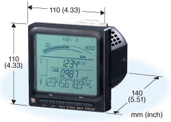
Figure 1. External Appearance and Dimensions of the 54U  (3-phase/4-wire Model)
Figure 1. External Appearance and Dimensions of the 54U
(3-phase/4-wire Model)
 

M-System’s model 54U is a panel mount 110mm-square (ANSI 4-inch round form size) Multi Power Monitor. One model can be used for single-phase/2-wire and 3-wire, three-phase/3-wire and 4-wire systems.

Key Functions and Features
(1) Measurement Variables

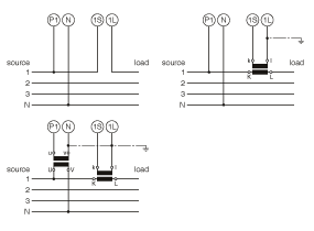
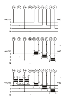
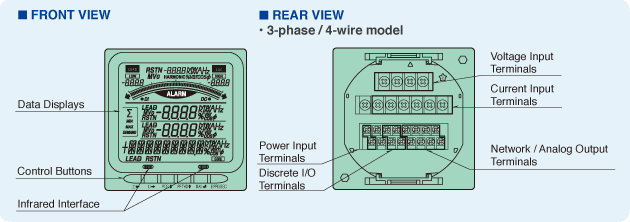
The 54U series’ terminal connection example shown in Figure 2 is for three-phase/4-wire system. Front and rear views are shown in Figure 3. Users can easily choose and program major variables from current, voltage, active, reactive, and apparent power, power factor, frequency, active and reactive energy, higher harmonics*1; and voltage phase difference. These measured variables are included in Table 1.

 
System /
Application
Terminal
Three-phase /
4-wire,
balanced load
Three-phase /
4-wire,
unbalanced load
Figure 2. Connection Diagram of the 54U (3-phase/4-wire Model)
 

In addition to the variables listed above, users can configure this advanced multi power monitor to measure and display the necessary measurements from a total of more than 450 possibilities, including tidal operations*2, four-quadrant operations*3, maximum value, minimum value, power demand, and count time.

(2) Open Collector Outputs
Open collector outputs can be set to generate either pulse or alarm output during energy measurement. Output options are selectable with 1 open collector output, 1 contact input, or 2 open collector outputs. (With this particular configuration, the 54U does not provide contact input.) The device also includes an output simulation function that makes it easy for the user to check connections at system startup.

(3) Contact Signal Input
Uses of contact signal input include demand value updating and energy reset trigger signals. Modbus communications may also be used to transmit on/off information along with measurement data to enable the monitoring of contact status.

(4) Modbus Communications and Analog Output
Users can select between Modbus communications and analog output. Modbus communication functionality provides the user with the ability to transmit measurement values for all parameters so that the necessary power data can be sent to upstream devices for collection and analysis. Communication functionality can be used to configure such aspects of device operation as display components and alarm values, and Modbus functionality can also be utilized with the 54U’s configuration software.

There are 4 analog outputs available and a measurement variable can be assigned to each. The 54U also provides a loop test function for setting output to a user-specified value.

Table 1. New Energy Measurement Variables
Description
Peak reactive energy (incoming)
Peak reactive energy (outgoing)
Peak active energy (incoming – outgoing)
Peak reactive energy (incoming + outgoing)
Off-peak reactive energy (incoming)
Off-peak reactive energy (outgoing)
Off-peak active energy (incoming – outgoing)
Off-peak reactive energy (incoming + outgoing)
 

(5) Front Display
The 54U’s front display uses an exceptionally well-designed LCD with a 1-line bar graph and 3 digital display lines. The bottom line incorporates an information function that displays an integrated value for measurements during normal operation and notifies the operator with flashing descriptive text in the event of an alarm.

The bar graph displays a user-specified measurement variable in the context of minimum and maximum value markers that can be set as desired. Since the alarm range is simultaneously displayed on the bar graph, both the measured value and alarm range can be clearly and accurately ascertained with a glance by the operator.

In addition, a home location display function reverts the display to a preset configuration when the unit has not been operated for a predetermined length of time.

Figure 3. 54U Panel Diagram
 
 
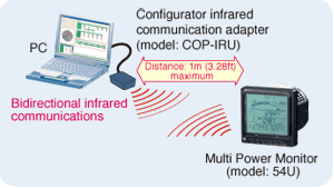
Figure 4. Configuration Using Infrared Communications
 
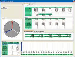
Figure 5. Example of 53UCFG Measured Value Display Screen

(6) Infrared Communications and Configurator
The 54U is compatible with an infrared communication adapter (model: COP-IRU) that allows various settings to be configured without the need to connect the 54U to a computer (see Figure 4).

The configuration software (model: 53UCFG; see Figure 5) can be downloaded from M-System’s website (https://www.m-system.co.jp/). This software’s functionality includes the ability to modify, download and upload parameters for the 53U and 54U Multi Power Monitors; manage parameter files; and compare edited and device parameters. Although it is possible to configure the same settings from the device’s front panel, the 53UCFG software simplifies the process.

*1: Higher harmonics up to the 31st order can be measured for current and voltage.
*2: Outgoing and incoming operations.
*3: Outgoing lead/lag and incoming lead/lag operations.


SALES TOPICS
 
R7FN
  • Remote I/O modules for Pro-face® FLEX NETWORK
  • Slave to Pro-face® Graphic Operator Interface:
    GP3000 Series
    GLC2000 Series
    LT Series Type B / B+ / C
  • 8 or 16 discrete signals
  • Simple setting
  • 1500 Vac isolation

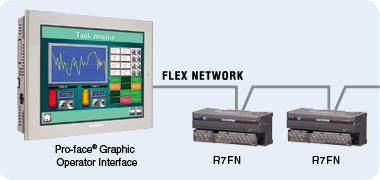
M-System’s R7FN Series Remote I/O modules directly interface with Pro-face® Graphic Operator Interface via FLEX NETWORK.

FLEX NETWORK
 

Palm-top size compact modules can handle sixteen discrete signals. Eight-point relay output module is also available.

These modules are designed to replace discontinued Pro-face® FLEX NETWORK slave modules (See the table below) with minimum differences in hardware. Furthermore, they can be identified with the discontinued model numbers by the Graphic Operator Interface master, thus simplifying software programming even when you have added the R7FN modules to an existing system.

1500 Vac isolation is maintained between I/O, network and power input.

Analog I/O modules will be also available in the future. For updated information, please contact M-System sales/customer support at info@m-system.co.jp.

Pro-face® is a registered trademark of Digital Electronics Corporation in Japan, U.S.A., Canada, Europe and other areas and countries.

Product Bulletins
A4: Letter:

MODEL SELECTIONS
M-System R7FN Series
FUNCTION MODEL
Discrete input, PNP/NPN, 16 points R7FN-DA16
NPN transistor output, 16 points R7FN-DC16A
PNP transistor output, 16 points R7FN-DC16B
Discrete input, PNP, 8 points /
NPN transistor output, 8 points
R7FN-DAC16A
Discrete input, NPN, 8 points /
PNP transistor output, 8 points
R7FN-DAC16B
Relay contact output, 8 points R7FN-DC8C
Pro-face Discontinued Products
FUNCTION MODEL
16-point input, sink/source type FN-X16TS41
16-point output, sink transistor FN-Y16SK41
16-point output, source transistor FN-Y16SC41
8-point input, sink/source type /
8-point output, sink transistor
FN-XY08TS41
8-point relay output FN-Y08RL41


Hotline News
Remote I/O R3 Series Proved Excellent Performance in
High Voltage, High Frequency Environments
 
R3 Series
 

The most important component in solar cells is highly purified silicon. Elkem Solar, Norway, produces solar grade silicon with much less energy consumption and CO2 -emissions, thus reduced Energy Pay-back Time (EPBT). The company is now industrializing its proprietary solar grade silicon production line on Elkem’s site in Kristiansand, Norway. The first plant at Fiskaa, opened August 21, 2009, will have a capacity of 6,000 tons of solar grade silicon after ramp-up.

The R3 Series Remote I/O has been tested and verified for use in temperature monitoring/control system (T/C, RTD, DC current/voltage, Di) in the refining process, where an induction heating/melting furnace is used. The monitoring/control system by Siemens PLC had been originally planned with Siemens I/O, but the R3 Series Remote I/O proved better performance in the high voltage, high frequency environment generated by induction coils.

‘High Voltage, High Frequency Environment’ is a keyword to success for M-System signal conditioners and remote I/Os. Thanks to their excellent isolation capability, they have been widely used in similar applications using induction heating/melting equipment, for example, thermal treatment process in steel mills, and vacuum sputtering machines in semiconductor manufacturing plants.


Application Notes

QThe dust eliminator is used at sand basin of sewage treatment plant. It is controlled to operate by comparing the water levels. Across the filter, water levels are compared and the dust eliminator is operated when the difference becomes greater. We are considering to use a deviation alarm that accepts signals from 2 sets of 2-wire type level sensors. Two relay outputs are used for alarming “water-level difference normal” and start operating the dust eliminator at “water-level difference abnormal”. It is also required the current loop supply as there is no power source available where sensors are installed.

A Click here for answer


M-System CALENDAR

Offices & Factory Closed
Please be aware M-System’s offices and factory will be closed on November 3 for national holiday. The day is Culture Day, a day for celebrating love of freedom and equality, and promoting culture.

Our offices and factory will also be closed on November 23 for Labor Thanksgiving Day.

October 2009
Mon Tue Wed Thu Fri Sat Sun
Sep 28

29

30 1 2 3 4
5 6 7 8 9 10 11
12 13 14 15 16 17 18
19 20 21 22 23 24 25
26 27 28 29 30 31 Nov 1
2 3 4 5 6 7 8
9 10 11 12 13 14 15
16 17 18 19 20 21 22
23 24 25 26 27 28 29


CLIPBOARD is a newsletter from M-System. Introducing new products, product literature and other important information we pick up in our daily business correspondence. Your comments, views and contribution are especially welcome.

M-System Co., Ltd
International Sales Department
Tel: +81-6/6659-8201 Fax: +81-6/6659-8510 Mail:info@m-system.co.jp