Information

The “CLIPBOARD” is the e-mail newsletter from M-System.
It introduces to you new products, literature, product applications and other important information we pick up in our daily business correspondence with clients around the world.
Your comments, views and contribution are welcome.


We would like to announce the issue schedule change for the “CLIPBOARD”. Some of its main articles are the English translations from our Japanese newsletter, the “MS TODAY”. Since May 1992, M-System has issued the monthly “MS TODAY”. Effective January 2010, the “MS TODAY” will be changed from A4 size to a new tabloid-type format. It will be improved in the information content, and the issuing schedule will be changed to a quarterly basis (4 times a year).

Accordingly, the “CLIPBOARD” will be also issued quarterly (4 times a year), and we will be adding some new topic items. However, the following changes will be in effect as well:
M-SYSTEM CALENDAR will be posted at the M-System’s rep site.
NEW PRODUCTS information and APPLICATION NOTES will be eliminated.


Seasonal Greeting
Kimono Party

Happy New Year!! We hope you enjoyed the holidays.

Shogatsu (The New Year season) is one of the most important days in Japan. We get together for greetings with family members, relatives, friends and colleagues!

This year, M-System International Operations staff gathered for the New Year's party. It was a lovely time for us, especially because we wore Kimonos. Although we dressed up in the traditional clothes, our homemade dishes were different from typical Japanese ones. There were multi-countries foods as fried rice from China, rice rolls from Korea, wine from Spain, cheese from Norway, British tea from England, and of course Japanese dishes. As M-System is the international company, so was our New Year's party. In 2010, we would like to achieve firm relationships with you from all over the world, and hope you have a wonderful 2010!


Featured Products-1
  • Model 71VR1 Compact Paperless Recorder
    (CE pending for the 71VR1-E501)
     
    1/4 DIN size (96 x 96 mm) panel mount compact recorder
  • 3.5 inch TFT color LCD display
  • Max. 8-point each of analog and discrete inputs are stored, displayed and alerted.
  • Max. 8-point discrete outputs can be assigned for alarm trips.
  • Direct field inputs at the built-in terminals and optional remote inputs via Modbus RTU
  • Data can be transferred to PC via the front IR port

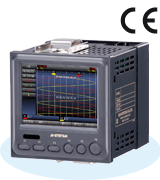
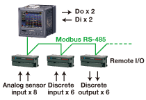
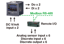
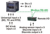
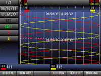
M-System’s Model 71VR1 is a 1/4 DIN size (96 x 96 mm panel cutout), compact paperless recorder that can store and display the maximum of 8-point analog inputs and 8-point discrete inputs. The 3.5 inch TFT color LCD display can show two pen channels at once on a trend graph or digital/bargraph indicators.
Field signals are connected to local terminals and polled remotely from Modbus RTU I/O devices. Three models are available depending on the number of local inputs:

  71VR1-E001 : Di x 2, Do x 2 and Modbus
  71VR1-E101 : Di x 2, Do x 2, DC mA/V input x 2 and Modbus
  71VR1-E501 : Di x 2, Do x 2, DC mA/V input x 2, universal input x 3 and Modbus

         
Remote I/O Type 71VR1-E001   DC Input Type 71VR1-E101   Universal Input Type 71VR1-E501


Memory Card & Safety Cover
   
 
The rear field terminal blocks are separable for easy wiring and installation.
The safety cover protecting against electrical shock is tethered with a strap.


Infrared Communication


Stored data can be uploaded to a PC using the Infrared Communication Adaptor.


Only 10 cm Behind the Panel


Thanks to its shallow depth of only 10 centimeters (4 inches) needed behind the panel surface*1, the 71VR1 can be mounted on control panels built into industrial and commercial machineries.

*1. Except that for personnel access


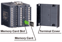
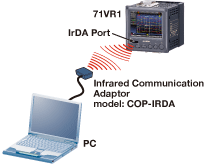
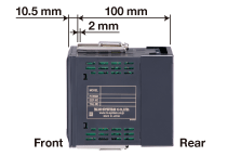
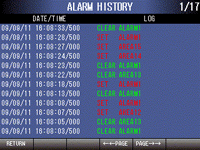
Data sampling rate is selectable between 100 msec. and 10 seconds depending upon the number of local and remote inputs. In addition to manual and continuous recording mode, conditional recording triggered by AND/OR functions in combinations of analog/discrete signal values/states is available. This allows the user to record only necessary part of the data in order to save memory area.

Each analog input signal is independently set with four (4) alarm thresholds. In addition to the built-in DO terminals, at the maximum of 8-point discrete outputs can be mapped on remote output devices to alert externally. Alarm events are recorded in an alarm history file, up to 200 events.

Data is stored in a memory card at the rear side of the recorder, and can be transferred to a PC and converted into CSV format files with this card or via the front IrDA port.

Thanks to its small panel size and shallow depth of only 10 centimeters (4 inches) needed behind the panel surface*1, the 71VR1 can be mounted on control panels built into industrial and commercial machineries. Imagine the 71VR1 mounted on a wave soldering machine. Single unit can monitor and record solder temperature, conveyor speed, starting/stopping of the machine, current consumption and their alarm history.

IP 65 front panel is also suitable for applications and installations where splashing water is present such as food and sanitary plants.

*1. Except that for personnel access

Product Bulletins
A4: Letter:


  Digital Indicators   Trend Graph   Alarm History  
  Digital Indicators   Trend Graph   Alarm History  
Clear & Legible Color Display


Featured Product-2
Figure 1. M2VF3 External Appearance
 

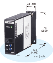
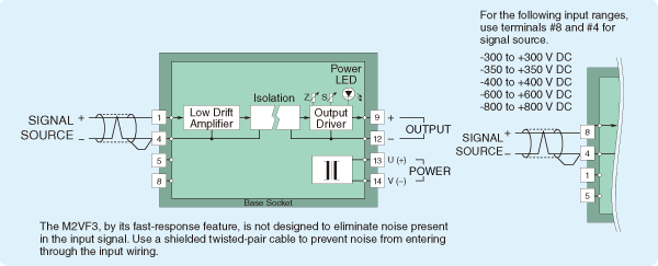
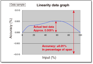
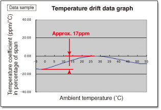
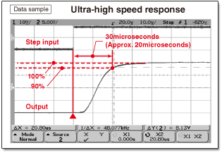
M-System’s M2 (Mini-M) Series Signal Transmitters are designed to accept a large range of process signal inputs and provide standard and nonstandard DC output. The M2 uses a plug-in socket base for quick installation or replacement of modules without disturbing wiring. (see Figure 1.)

The M2VF3 is designed with various high performance features.

  • Wide input DC voltage range is available to specify from min. -20 to +20mV up to -800 to +800V (see Table 1.)
  • High accuracy: ±0.01%, Temp. coefficient: ±0.005%/°C , in percentage of span
  • Ultra-high speed response: Less than 30 microseconds (0 to 90%)
  • Zero/span adjustors at front cover: ±1% (zero adjustment) 99 to 101% (span adjustment)
  • Low power consumption (24V DC power input): 0.4W at input resistance 1MΩ, 0.5W at 2KΩ
  • 2000 Vac three-way isolation (input to output to power to ground)
Table 1. Main specifications of M2VF3
Input
-20 to +20mV DC
-24 to +24mV DC
-40 to +40mV DC
-85 to +85mV DC
-100 to +100mV DC
-164 to +164mV DC
-200 to +200mV DC
-5 to +5V DC
-10 to +10V DC
-15 to +15V DC
-20 to +20V DC
-25 to +25V DC
-55 to +55V DC
-60 to +60V DC
-300 to +300V DC*
-350 to +350V DC*
-400 to +400V DC*
-600 to +600V DC*
-800 to +800V DC*
* CE not available  
Output
-10 to +10V DC
Power Input
24V DC
Response Time
≤30 microseconds (0 – 90%)
(except the user specified ranges)
Frequency Characteristics
12 kHz, -3 dB
 

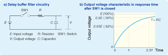
In control theory, the time of output changes from a former setpoint to new setpoint in response to the change of input in step is called “step response time”. M-System’s data sheet is defining response time of a voltage to rise from 0% to 90% of its peak value.

The input circuitry of M2VF3 is designed per Figure 2., resistor in series to input signal and capacitor in parallel to input signal, that the response characteristic is similar to lowpass filter’s “delay buffer”.

When applied an input signal of square wave to lowpass filter’s “delay buffer”, the frequency at output signal’s bandwidth attenuated to -3dB is called “cutoff frequency”. Time constant t is as shown per formula #1.
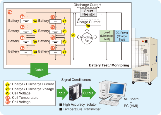
t (s)= R (Ω) · C (F) --- formula #1
Response time (T) is as shown per formula #2.
T = 2.3 t --- formula #2
Cutoff frequency ƒ is as shown per formula #3.
ƒ = 1/ (2 p t) --- formula #3
Cutoff frequency at 30 microseconds response time is calculated as below.
By using formula #1 as t = T/2.3, when T is 30microseconds t ≈ 13μs
Then a calculating result of ƒ by formula #3 becomes
ƒ ≈ 12.2kHz
Higher the cutoff frequency the response time is faster.

 
Figure 2. Response time of delay buffer filter
 
Figure 3. Schematic circuitry & connection diagram of M2VF3


Benefits of using M-System signal isolator to meet A/D conversion criteria

Application example
The battery test system is used for evaluating advanced batteries or capacitors in hybrid vehicles. The main feature of system is to conduct charging and discharging tests for batteries. Monitoring process includes voltage, current, temperature, etc., which are measured by signal conditioners and transmitted to PC system.


Figure 3. Schematic circuitry & connection diagram of M2VF3
 

Benefits of using M-System signal isolator to meet A/D conversion criteria

  • High accuracy (linearity and low temperature drift)
  • Ultra faster response time is required for a signal conditioner to cover the fast data sampling by analyzing software (HMI) e.g. 1kHz which to monitor transient voltage changes at sudden load change, open circuitry, physical destruction and etc.
  • Dielectric strength for high frequency noise
  • Low power consumption
     
Linearity data graph  
Temperature drift data graph
     
Ultra-high speed response    


Application Notes

QFor the production of pasta, there is a mixing process of raw materials in a tank. The raw materials can be affected by heat. To prevent it, the water temperature surrounding the tank is adjusted by controlling the valves of cold-water and heated-water. This time, we are considering a PLC to control the temperature automatically. The DeviceNet communication bus is ideal to control the valves. Is there any suitable product?

A Click here for answer


M-System CALENDAR

Offices & Factory Closed
In February, M-System's offices and factory will be closed on February 11 for National Foundation Day.
March 21 is Vernal Equinox Day, so we will get substitute public holiday on next Monday March 22.

In April, our offices and factory will be closed on April 29 for Showa Day, it is the Emperor Showa's birthday.

Please be aware from May 3 through May 5 for a series of national holidays, we will be back again on Thursday May 6.

We will appreciate it if you would kindly keep this in mind when you discuss delivery time with your customers.

January 2010   February 2010
Mon Tue Wed Thu Fri Sat Sun


1

2 3
4 5 6 7 8 9 10
11 12 13 14 15 16 17
18 19 20 21 22 23 24
25 26 27 28 29 30 31
 
Mon Tue Wed Thu Fri Sat Sun

1

2 3 4 5 6 7
8 9 10 11 12 13 14
15 16 17 18 19 20 21
22 23 24 25 26 27 28
     
March 2010   April 2010
Mon Tue Wed Thu Fri Sat Sun

1

2 3 4 5 6 7
8 9 10 11 12 13 14
15 16 17 18 19 20 21
22 23 24 25 26 27 28
29 30 31        
 
Mon Tue Wed Thu Fri Sat Sun


1

2 3 4
5 6 7 8 9 10 11
12 13 14 15 16 17 18
19 20 21 22 23 24 25
26 27 28 29 30    
     
May 2010    
Mon Tue Wed Thu Fri Sat Sun


1

2
3 4 5 6 7 8 9
10 11 12 13 14 15 16
17 18 19 20 21 22 23
24 25 26 27 28 29 30
31            


CLIPBOARD is a newsletter from M-System. Introducing new products, product literature and other important information we pick up in our daily business correspondence. Your comments, views and contribution are especially welcome.

M-System Co., Ltd
International Sales Department
Tel: +81-6/6659-8201 Fax: +81-6/6659-8510 Mail:info@m-system.co.jp