| EAP-032047 |
 What
is "CUTOUT" function of new frequency transmitters? Is it not
"LOW-END CUTOUT"? What
is "CUTOUT" function of new frequency transmitters? Is it not
"LOW-END CUTOUT"? |
 |
 M-System's conventional frequency transmitters have a "LOW-END CUTOUT"
function by which a frequency input lower than a certain level (e.g. 5%
F.S.) is forcibly output as zero. This is beneficial to eliminate ripples
contained in pulse signals. M-System's conventional frequency transmitters have a "LOW-END CUTOUT"
function by which a frequency input lower than a certain level (e.g. 5%
F.S.) is forcibly output as zero. This is beneficial to eliminate ripples
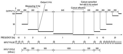
contained in pulse signals.Now in order to explain the "CUTOUT", we must know about "Sampling Time" first. The sampling time is the period of time during which the input pulse is measured. It is set as a specific value, but in actual measuring*, the value changes according to input frequency. |
|
 |
|
| For example, suppose that you have the
sampling time 200 millisec. (default) and the cutout time 640 millisec.
(user specified). When the input cycle (inverse value of input frequency)
is shorter than the preset 200 millisec. (higher frequency), the transmitter
renews the output signal every 200 millisec. On the contrary, when it is
longer than 200 millisec. (lower frequency), the sampling time is prolonged,
and the measuring is over after an appropriate time, with the output renewed.
Then if a further longer cycle comes, the sampling time is also prolonged.
When this continues, the sampling time eventually becomes too long, without
an output renewal. The cutout time is set so that the transmitter forcibly
discontinues a sampling cycle and outputs as 0 Hz. Both sampling time and cutout time are adjustable with the Programming Unit (PU-2A). It is hardly necessary to change the sampling time from the default, but the cutout time must be carefully selected because it is closely related to your requirement for the longest measurable cycle. Let's see what will happen if you set the cutout to an inappropriate value: Frequency range is 100 Hz to 10k Hz. You set the cutout to 100 seconds. When the input signal is suddenly lost, the transmitter will continue to output the previous value for as long as 100 seconds! *The sampling time is constant with pulse accumulating type transmitters (JPQD, JRQD). |
| M-System has flexible solutions to meet your specific application and requirements. Consult our Signal Conditioners Data Library. |
| Copyright © 2003 MG Co., Ltd. All rights reserved. |