| EAP-032052 |
 It is unlikely that the JF is failed in this case. It would be rather because
you may have used only one signal generator and connected the JF to it as
shown in Figure 1. It is unlikely that the JF is failed in this case. It would be rather because
you may have used only one signal generator and connected the JF to it as
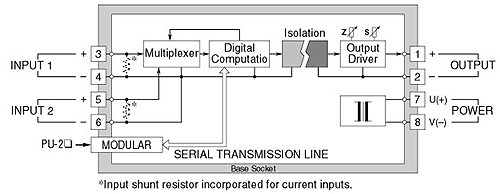
shown in Figure 1.As you can see in the block diagram shown in Figure 2, the minus side of JF's Channel 1 input and Channel 2 input is connected to the common negative. Therefore, there is no current flow at the Channel 2 input if you connect the signal generator as in Figure 1. The 4-20 mAdc from the signal generator, according to the diagram, reaches the terminal No.3 and is diverted to the terminal No.6 through the resistor in the module and the minus common line. Therefore, the Channel 2 input shows Zero. When calibrating the JF, two sets of signal generators are required. |
|
 Figure 2: Circuit diagram of model JF |
| M-System has flexible solutions to meet your specific application and requirements. Consult our Signal Conditioners Data Library. |
| Copyright © 2003 MG Co., Ltd. All rights reserved. |