| EAP-0320117 |
| Water Distribution Facilities | |
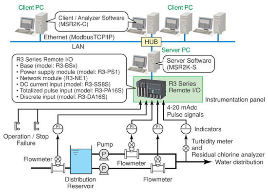
M-System’s MSRpro is a ‘paperless pen-type’ recording system for PC-based data acquisition and analysis, supporting a total of 2048-channel analog and discrete signals. By communicating with I/O modules that have a LAN card communication interface, the MSRpro reads input signals and stores them in a hard disk as digital data. The MSRpro is a suite of three programs: the MSRpro-Server (referred hereafter as ‘Server’), MSRpro-Builder (‘Builder’), and the MSRpro-Client/Analyzer (‘Client’). This software package provides a simple solution while still maintaining the wide versatility of available types of signal combinations that has made M-System a vendor of choice in many applications around the world. Success Story – Waterworks Department
– Water Distribution Facilities
Connecting client PCs over Ethernet to a server PC in the field, a maximum of 4 client PCs are available for real time monitoring of field sensors. Converting stored data in the server into a CSV file is available. R3 series’ remote I/O was used to accept field signals. The R3-SS8S, or DC current input card, was used to input 4-20 mAdc signals from the flow meters. Under the basic mode setting, input signals are displayed on the trend view, using a variety of engineering units. When using the operation function, data undergoing a certain type of operational change can be plotted. The R3-PA16S, totalized pulse input card, is used to input pulse signals from flow meters. The customer also needed to monitor the pump’s operation/stop, failure and other functions, so the R3-DA16S discrete input cards were used to display an alarm view. The alarm history will appear with time stamps as determined by the builder software for alarm events, start/stop of pumps and other events. Alarm events are initially shown in red. Under the heading of Acknowledge, the user is able to click on an appropriate cell to acknowledge an alarm. Once it is acknowledged, the relevant cell turns to green.
|
| Copyright © 2005 MG Co., Ltd. All rights reserved. |