New features added to split-range control transmitter |
||||||||||||
1. Definition A Split-range transmitter is used to provide control (split-range control) over 2 or more different elements using one input signal. For example, in a heated swimming pool, the water temperature is the input signal and the two controlled elements are hot and cold water supply valves. Below figure 2 illustrates the MFS2 series’ selectable output characteristics, V-shape or Parallel, depending on the user’s application requirements. In the heated swimming pool example, user would select V-shaped characteristics using the pool’s water temperature as the input signal, V1 as the cold water supply valve control signal, and V2 as the hot water supply valve control signal.
2. MFS2 Features and Functionality
The MFS2 is a split-range transmitter with 1 analog input and 4 analog outputs available (See Figure 3 for a block diagram of the MFS2). The unit is capable of using 1 input signal to control 4 different elements. In addition to controlling the hot and cold water supply valves, in the aforementioned example, by utilizing the isolation feature between input and output, the MFS2 could also be used for the pool’s water temperature monitoring (limit alarm instrument), and for the display of the pool’s water temperature (display instrument). The MFS2 features allow users to set different I/O characteristics for each of its 4 outputs. From a safety instrumentation perspective, it also provides functionality for setting upper and lower limit values for each output. The MFS2 also has a contact input. This feature provides forced output of a preset value in response to a contact input status of either closed or open. This is beneficial in applications where it is necessary to force 0% output in emergency situations.
3. Simple PC-based Configuration The functions described in this article can be easily configured using our dedicated software "PC Configurator" (model: MFS2CFG)*.
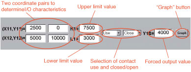
The following settings are available for each output channel:
Customers can easily accommodate changes in applications by modifying these settings. Figure 4 provides a specific setting example using the following values:
4. Graph-based Confirmation of Settings
Figure 5 displays the Figure 4 settings in graph form. Black circles on the graph indicate coordinates that determine input to output characteristics. With the upper and lower limit values applied, the red line indicates the input to output characteristics. Note: Our plans to make the PC Configurator software available for download from its website (https://www.mgco.jp/). A dedicated PC Configurator cable (model: MCN-CON) is required to connect the MFS2 to user’s computer. |
||||||||||||