| Low Speed Totalized Pulse Input Module (4 points, isolated) | |||
| Model R3-PA4B | Release : NOW | RoHS | |
| Delivery : 7 working days | Spec |
||
| Strain Gauge Input Module (2 points, isolated) | |||
| Model R3-LC2 | Release : NOW | RoHS | |
| Delivery : 7 working days | Spec |
||
| Multi Power Input Module (clamp-on current sensor type CLSE use) | |||
| Model R3-WTU | Release : NOW | RoHS | |
| Delivery : 7 working days | Spec |
||
| Discrete Input Extension Module, 8 points (CC-Link V.1.10) | |||
| Model R7C-EA8 | Release : NOW | RoHS | |
| Delivery : 9 working days | Spec |
||
| Discrete Input Extension Module, 8 points (DeviceNet) | |||
| Model R7D-EA8 | Release : NOW | RoHS | |
| Delivery : 9 working days | Spec |
||
| Discrete Input Extension Module, 8 points (Modbus) | |||
| Model R7M-EA8 | Release : NOW | RoHS | |
| Delivery : 9 working days | Spec |
||
| NPN Transistor Output Extension Module, 8 points (CC-Link V.1.10) | |||
| Model R7C-EC8A | Release : NOW | RoHS | |
| Delivery : 9 working days | Spec |
||
| NPN Transistor Output Extension Module, 8 points (DeviceNet) | |||
| Model R7D-EC8A | Release : NOW | RoHS | |
| Delivery : 9 working days | Spec |
||
| NPN Transistor Output Extension Module, 8 points (Modbus) | |||
| Model R7M-EC8A | Release : NOW | RoHS | |
| Delivery : 9 working days | Spec |
||
| PNP Transistor Output Extension Module, 8 points (CC-Link V.1.10) | |||
| Model R7C-EC8B | Release : NOW | RoHS | |
| Delivery : 9 working days | Spec |
||
| PNP Transistor Output Extension Module, 8 points (DeviceNet) | |||
| Model R7D-EC8B | Release : NOW | RoHS | |
| Delivery : 9 working days | Spec |
||
| PNP Transistor Output Extension Module, 8 points (Modbus) | |||
| Model R7M-EC8B | Release : NOW | RoHS | |
| Delivery : 9 working days | Spec |
||
| Analog Backup Station | |||
| Model JB2 | Release : NOW | ||
| Delivery : 5 working days | Spec |
||
| Current Loop Supply (non-isolated), UL Approval | |||
| Model M2D2 (/UL) | Release : NOW | RoHS | |
| Delivery : 5 working days | Spec |
||
| Current Loop Supply (with square root extractor; isolated) , UL Approval | |||
| Model M2DNY (/UL) | Release : NOW | RoHS | |
| Delivery : 5 working days | Spec |
||
| Current Loop Supply (isolated), UL Approval | |||
| Model M2DYS (/UL) | Release : NOW | RoHS | |
Delivery : 5 working days |
Spec |
||
| Strain Gauge Transmitter, UL Approval | |||
| Model M2LCS (/UL) | Release : NOW | RoHS | |
| Delivery : 5 working days | Spec |
||
| Limiter, UL Approval | |||
| Model M2LMS (/UL) | Release : NOW | RoHS | |
| Delivery : 5 working days | Spec |
||
| Pulse Scaler (selectable range), UL Approval | |||
| Model M2PRU (/UL) | Release : NOW | RoHS | |
| Delivery : 5 working days | Spec |
||
| Ratio/Bias Transmitter (output bias), UL Approval | |||
| Model M2REB (/UL) | Release : NOW | RoHS | |
| Delivery : 5 working days | Spec |
||
| Ratio/Bias Transmitter (input bias), UL Approval | |||
| Model M2RTS (/UL) | Release : NOW | RoHS | |
| Delivery : 5 working days | Spec |
||
| Signal Transmitter (ultra-high speed response; isolated), UL Approval | |||
| Model M2VF2 (/UL) | Release : NOW | RoHS | |
Delivery : 5 working days |
Spec |
||
| Encoder Speed Transmitter (PC programmable; built-in escitation), UL Approval | |||
| Model M2XRP2 (/UL) | Release : NOW | RoHS | |
| Delivery : 6 working days | Spec |
||
| Current Loop Supply (with square root extractor; isolated), UL Approval | |||
| Model W2DNY (/UL) | Release : NOW | RoHS | |
| Delivery : 5 working days | Spec |
||
| Current Loop Supply (isolated), UL Approval | |||
| Model W2DYS (/UL) | Release : NOW | RoHS | |
| Delivery : 5 working days | Spec |
||
| DC Input Digital Panel Meter (4 1/2 digit, LED display type) | |||
| Model 47LYV | Release : NOW | RoHS | |
| Delivery : 7 working days | Spec |
||
R7ML Remote I/O Now Supports Yaskawa Electric's MECHATROLINK-I and -II Motion Control Communication Bus |
|
||||||||||||||||||||||||||||||||||||||||||||||||||||||||||||||||||||||||||||||||||||||||||||||||||||||||||||||||||||||||||
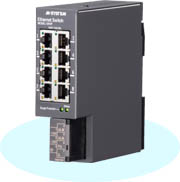
| AC Power Input (AC100V - 240V) is available with model SHSP, 8-Port Ethernet Switch with Surge Protector | ||||||||||||||||||||||||||||||||||
Model SHSP has been well received by customers since it was released in 2007. While marketing it, we have been receiving customers’ requests for AC power input. Applications are to use with PC in their plants and buildings. Customers are considering the necessity of surge protection from a lightning surge enters the LAN cable. Newly added AC power input code will cover AC100V - 240V. Its official release is scheduled by end of 2008. For further information, please reach us at your convenience. |
||||||||||||||||||||||||||||||||||
|
||||||||||||||||||||||||||||||||||
Offices & Factory Closed Please be aware that in November, our offices and factory will be closed on November 3 for national holiday. The day is Culture Day, a day for celebrating love of freedom and equality, and promoting culture.
|
|
CLIPBOARD is a newsletter from M-System. Introducing new products, product literature and other important information we pick up in our daily business correspondence. Your comments, views and contribution are especially welcome. |
| International Sales Department Tel: +81-6/6659-8201 Fax: +81-6/6659-8510 Mail:info@m-system.co.jp |
| Copyright (C) 2008 M-System Co., Ltd. All rights reserved. |