| EAP-031086 |
 I
am looking for a signal conditioner which can output either 0 or 10 Vdc
by switching ON-OFF contact. I
am looking for a signal conditioner which can output either 0 or 10 Vdc
by switching ON-OFF contact. |
 |
 You
can use the Potentiometer Transmitter model M2MS. You
can use the Potentiometer Transmitter model M2MS.
See Figure 1. The Potentiometer Transmitter has a built-in excitation voltage source of 0.5 Vdc. When the switch is turned to the side "a", 0.5 V is input to the transmitter, while it's turned to the side "b", 0 V is input. Now if you choose the transmitter output 0-10 V, it provides 10 V for the "a" and 0 V for the "b". You can have other signals like 4 mA and 20 mA by choosing other output ranges. |
|||
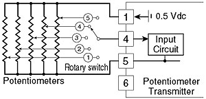
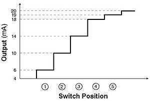
| Advanced Application: Advantages of utilizing potentiometers are their low cost and variety of types. By combining a 5-position rotary switch and five (5) potentiometers, you can have five (5) different analog signals with one (1) Potentiometer Transmitter. Connection diagram is shown in Figure 2 and relation of switch positions and output signals is shown in Figure 3. | |||
 Figure 2 |
|||
 Figure 3 |
|||
How To Determine Output Signal:
Suppose you have a 1k ohms potentiometer for the above example.
The resistance value for switch position No. 4 is given as 875 ohms with
the following equation:
V1 = 0.5V x {(18-4) / (20-4)} V1 = 0.4375 (Vdc) V1 = 0.4375 V equals 87.5% of the range 0-0.5 V, which equals 875 ohms for the range 0-1k ohms. {(18-4 mA) / 16 mA x 100 = 87.5%} |
|||
| M-System has flexible solutions to meet your specific application and requirements. Consult our Signal Conditioners Data Library. |
| Copyright © 2003 MG Co., Ltd. All rights reserved. |