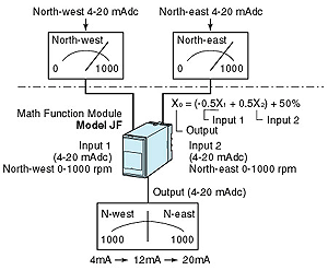
 Your current measuring system is assumed to be shown above the chain line
in the figure below. Your current measuring system is assumed to be shown above the chain line
in the figure below.
The meters accept 4 - 20mA DC signal to show wind speed for respective wind
direction. To unify these signals to indicate on a meter, use our Math Function
Module (model: JF). The system configuration is shown under the chain line
in the Figure below.
Connect 4 - 20mA DC signals from each direction to JF input. Specify addition/subtraction
for JF equation, gain/bias parameters, and the output will be provided as
4 - 20mA DC signal. The equation is as follows:
X0 = K0{K1(X1+A1)
+K2(X2+A2)}+A0
(X0: output, X1, X2:
input, K0, K1, K2:
gain, A1, A2, A0:
bias) |
In this case, specify K0=1, K1=-0.5,
K2=+0.5, A0=50%, A1=0%
and A2=0%, and the signal will represent 1000 rpm
north-east with 20mA output and 1000 rpm north-west with 4mA output, with
12mA DC as borderline. |
 Your current measuring system is assumed to be shown above the chain line
in the figure below.