| EAP-032069 |
| Watt Transducer- Model LTWT | |
 How to determine the VT input value for 3-phase/4-wire configuration for
M-System's watt transducers such as the model LTWT? How to determine the VT input value for 3-phase/4-wire configuration for
M-System's watt transducers such as the model LTWT? |
 |
  Please
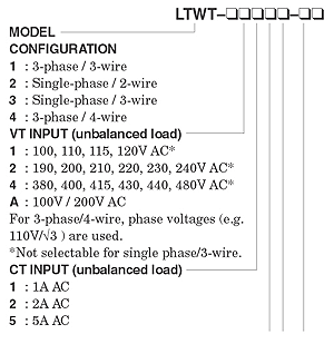
refer to note under the VT input selections regarding 3-phase/4-wireconfiguration(See
the model & suffix code selection to the right.) Please
refer to note under the VT input selections regarding 3-phase/4-wireconfiguration(See
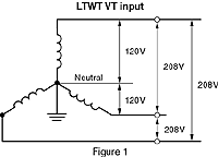
the model & suffix code selection to the right.)For 3-phase/4-wire, the phase voltage (line to neutral) is calculated as the result of line voltage (line to line voltage) divided by root 3. See Figure 1. Above example applys to: 208V / root 3 = 120V And, the VT input for LTWT is by line voltage select code 2: 190, 200, 210, 220, 230, 240V AC. |
|
 |
| M-System has flexible solutions to meet your specific application and requirements. Consult our Signal Conditioners Data Library. |
| Copyright © 2003 MG Co., Ltd. All rights reserved. |