| EAP-032125 |
| Data Acquisition from Fuel Cell Test Equipment | |
Success Story — DATA ACQUISITION FROM FUEL CELL TEST EQUIPMENT
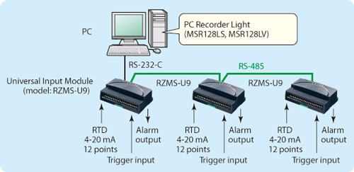
Signals are RTDs from temperature sensors and 4-20mA DC from pressure sensors. The model RZMS-U9, with 12 points universal input, will be used providing channel to channel isolation, remote trigger and alarm outputs. Three units of RZMS-U9 are networked over RS-485 (Modbus RTU). (Figure 1)
In conjunction, the PC recorder software to be used is the MSR128-Light (MSR128LV, MSR128LS). The MSR128-Light is designed to operate on a PC with relatively low performance. Even a Windows 98 PC may be utilized, though certain functions of the MSR128 which require the PC’s high performance, will not be available. MSR128LV, MSR128LS service channel numbers 120 maximum, using Group 1 through Group 10 views (12 channels/group). A data file is created per group and may be saved in CSV format allowing for easy export to other Windows programs such as Microsoft Excel.
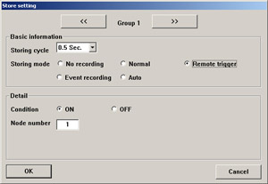
Remote Trigger mode (Figure 2): The MSR128-Light stores data only when a predetermined condition is true (the remote trigger contact signal is either ON or OFF). • Condition: Specify whether the recorder should identify ON or OFF of the contact signal as a trigger condition. For example, when the State is set to ON, the MSR128-Light stores data while the signal is ON and stops recording when it is turned to OFF. • Node Number: Specify which device connected to the MSR128-Light is used to trigger the recording. In our case, the trigger input terminal equipped on the analog input module, the RZMS, is used.
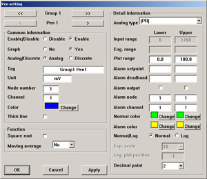
Alarm Setpoint (Figure 3) Alarm Node & Channel These are just a few of the features of the MSR128-Light and RZMS that have come to be highly regarded by customers along with providing a cost effective solution for their needs. |
| Copyright © 2007 MG Co., Ltd. All rights reserved. |