Digital Panel Meters
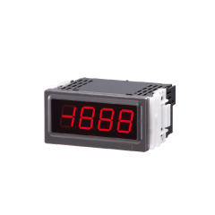
47L Series (LED display type)
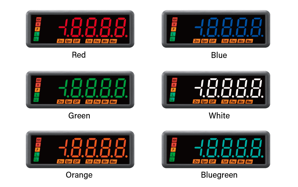
LED Display with Six Display Color Variations
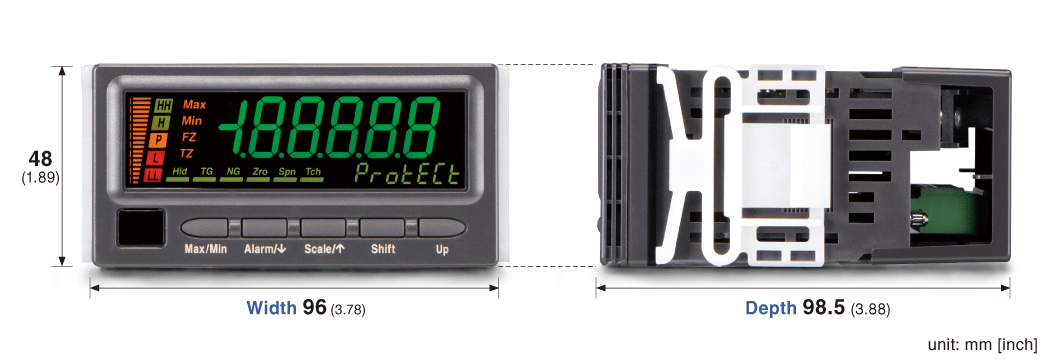
- 1/8 DIN size (96 x 48 mm), 4 1/2 digit digital panel meter
- LED color selectable: Red, Orange, Green, Bluegreen, Blue, White
- Field-selectable input range
- 100-240 V AC or 24 V DC powered
- Options: alarm, transmitter output
- IP66 front panel
- Separable terminal block


Depending on the model.
-
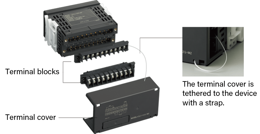
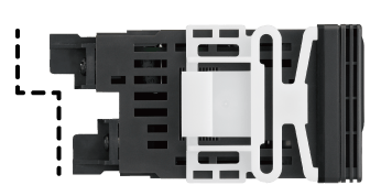
Separable Terminal Blocks
Thanks to a 2-piece detachable terminal block design, there is no need to disconnect numerous cables from the terminal blocks when removing the device from the panel for inspection or maintenance purposes.
-
Easy Access to Screw Terminals
Vertically staggered terminal blocks on the rear of the case make wiring works easy and help keep connected cables from becoming tangled.
-
Bright, Clear, and Colorful Displays
Users may specify a variety of display colors in addition to standard red and green configurations, including orange, blue-green, blue, and white, making it easy to customize the meters for use in unique applications.
-
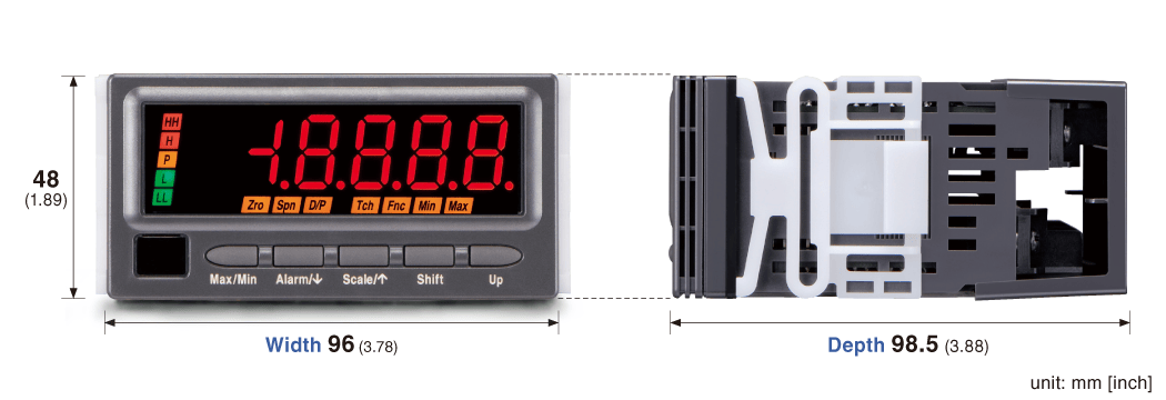
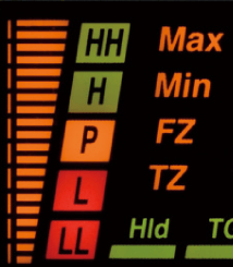
Front Panel (Model: 47LV)
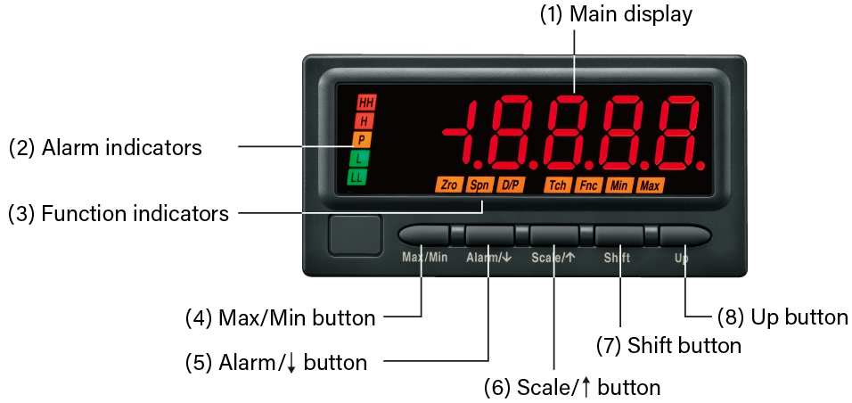
No. Component Functions (1) Main display Indicates present values, setting values and status of the unit. (2) Alarm indicators Indicate alarm status of the input signal. (3) Function indicators Indicate the status in each setting mode. (4) Max/Min button Used to switch the main display to show the present values, maximum values or minimum values etc. (5) Alarm /↓button Used to confirm alarm setting value and to move on to the alarm and other setting modes; or to shift through setting items in each setting mode. (6) Scale /↑button Used to move on to the scaling and other setting modes; or to shift through setting items in each setting mode. (7) Shift button Used to move on to the setting standby status of each setting mode and shift through display digits in each setting mode. (8) Up button Used to change setting values, to execute/cancel Forced Zero or to select setting values. Note: Refer to the operating manual for details on each function.
-
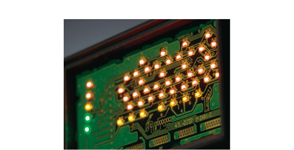
High-Brightness LED
High-brightness LEDs are used to create a display that is bright, clear, and sharp.
-
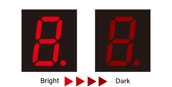
Brightness Adjustment
The display brightness can easily be set by the user to any of 5 levels to match the environment in which the meter is being used.
Digital Panel Meters
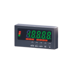
47D Series (LCD display type)
LCD Display with Multiple Functions
- 1/8 DIN size (96 x 48 mm), 5 1/2 digit digital panel meter
- Red or Green LCD selectable (negative type LCD with LED backlight)
- Field-selectable input range
- Excitation supply +12 V, +24 V
- 100-240 V AC or 24 V DC powered
- Options: alarm, transmitter output, BCD, RS-485 / Modbus RTU, event trigger input
- IP66 front panel
- Separable terminal block
Depending on the model.
-
Separable Terminal Blocks
Thanks to a 2-piece detachable terminal block design, there is no need to disconnect numerous cables from the terminal blocks when removing the device from the panel for inspection or maintenance purposes.
-
Easy Access to Screw Terminals
Vertically staggered terminal blocks on the rear of the case make wiring works easy and help keep connected cables from becoming tangled.
-
Bargraph Covering the Full Display Range at a Glance
The input signal level is visualized by a small bargraph, which helps the user intuitively grasp the present status.
-
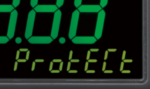
Convenient Sub Display Helps Setting Work
The sub display shows setting items and values during setting work. Text information helps you to configure the meter without needing an instruction manual.
-
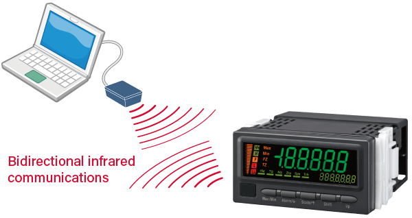
Infrared Communications
The 47D Series models support an infrared communication adaptor (Model: COP-IRU, separately purchased), used to configure the meters from a computer. Setting data can be downloaded to/uploaded from a PC. Data can be saved as a file in a PC for easy management: standardization and recording. PC Configurator Software (Model: 47DCFG) can be downloaded for free from our website.
-
Modbus Communication (option)
Modbus communication is supported as optional. Measured values and alarm status can be monitored by a PC or a PLC. Setting can be performed also by the host device via Modbus.
-
Excitation Supply
The 47D Series includes an excitation supply. Users can choose from two-wire transmitter excitation (+24 V) and sensor excitation (+12 V) at the time of purchase (except for 47DAC).
-
Front Panel (Model: 47DV)
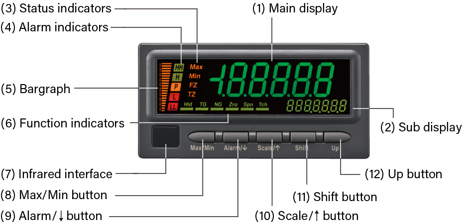
No. Component Functions (1) Main display Indicates present values, setting values and status of the unit. (2) Sub display Indicates the present setting mode. (3) Status indicators Indicate Max/Min display mode, Forced zero mode and Tare adjustment mode. (4) Alarm indicators Indicate alarm status of the input signal. (5) Bargraph Indicates present signal level against the scaled range. (6) Function indicators Indicate the device status. (7) Infrared interface Used for the infrared communication. (8) Max/Min button Used to switch the main display to show present values, maximum values or minimum values etc. (9) Alarm /↓button Used to confirm alarm setpoints and to move on to the alarm and other setting modes; or to shift through setting items in each setting mode. (10) Scale /↑button Used to move on to the scaling and other setting modes; or to shift through setting items in each setting mode. (11) Shift button Used to move on to the setting standby status and shift through display digits in each setting item. (12) Up button Used to change and apply setting values; or to execute/cancel Forced Zero and tare adjustment. Note: Refer to the operating manual for details on each function.